Posted by Admin | Leave a Comment
Circuit Description
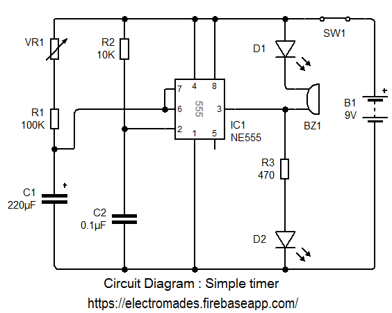
When the circuit is switched on, IC 555 timer starts timing. The green LED lights to show that timing is in progress. When the time period is over the green LED turns OFF, the red LED turns ON and the buzzer sounds. The time period is set by adjusting the variable resistor VR1. Time can be adjusted from 1 to 10 minutes (approximately). The time is extended to about 10 minutes because the 220µf timing capacitor slowly leaks charge. This is a problem with all electrolytic capacitors, but some leak more than others.
Circuit Diagram

Components Required
1. Push to on switch
2. Capacitor C1-220µF/25v and C2- 0.1µF/25v
3. Resistance-
Variable resistance- VR1-100kΩ
R1- 100kΩ
R2- 10kΩ
R3- 470Ω
4. IC 555 TimerR1- 100kΩ
R2- 10kΩ
R3- 470Ω
5. D1(LED-Red), D2(LED-Green)
6. Battery 12v DC
Comments & Related items
Popular Posts : Automatic Light | Electronic Dice | Direction Indicator | Fire Alarm | Touch Switch