Posted by Admin | Leave a Comment
Circuit Description
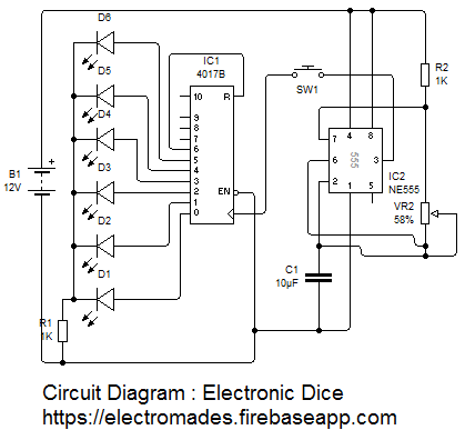
A Electronic dice is a good alternative of old fashioned dice, because Generally dice is made up of wooden or plastic, which gets deformed with time and become biased.Dice is used to play games like snake ladder, Ludo etc.This Dice consists of IC 555 timer and IC 4017 Decoded Decade Counter.This circuit consists of 6 LEDs, each LED represent a number (1-6) of Dice. LEDs start flashing as you will press the Push button and stops when we release it. After release, illuminated LED tells the numbers, you got on Dice. Like if second no. LED remains ON after releasing the button, means you got 2 on Dice. We have connected 6 LEDs to the output Q0 to Q5, and the seventh output Q6 is connected back to the RESET PIN 15. So that after LED 6 it starts from the First LED at Q0.
To apply the clock pulse at PIN 14 of 4017 IC, we have used 555 timer IC in A stable mode. The oscillated output generated at PIN 3 of 555 has been applied to the PIN 14 of 4017, so that output can be advanced with each clock pulse. We can control the speed of flashing LEDs by using the potentiometer (RV1), rotating the potentiometer knob will change oscillation frequency so that no one can cheat.
Circuit Diagram

Components Required
1. Resistances-
R1- 1KΩ
R2- 1KΩ
Variable Resistor - 10KΩ
2. Capacitor-R2- 1KΩ
Variable Resistor - 10KΩ
C1-10µF
3. IC 555 Timer4. IC 4017 Decoded Decade Counter
5. LED (D1-D6)
6. Push Switch
7. 9V DC Battery
Comments & Related items
Popular Posts : Automatic Light | Cut Off Timer | Direction indicator | Fire alarm | Touch Switch