Posted by Admin | Leave a Comment
Circuit Description
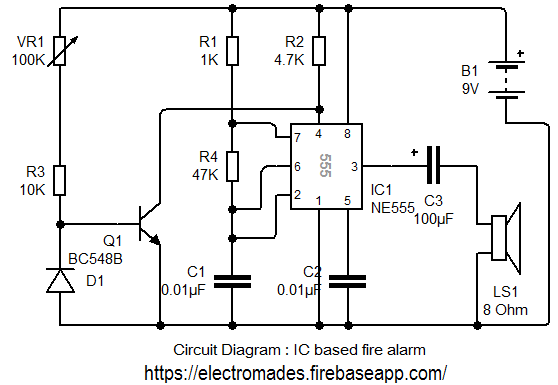
Here, an IC based fire alarm is described. Which is made to sense fire or heat at any place. It uses IC 555(timer) and germanium Diode as a heat sensor. A reverse based germanium diode is used here as a heat sensor as told previously.
At room temperature the diode has very high reverse resistance (over 10kΩ). No effect is produced by it on transistor T1, which conducts and beeps the reset pin 4 of IC at ground level and so the alarm does not sound.
When temperature in the vicinity of diode D1 (the sensor) increases in case of fire, the reverse resistance of D drops. At about 70°C its resistance drops to a value below 1 kΩ.This stops Transistors conduction, the IC's reset pin 4 become positive through resistor R, which sounds alarm.
Circuit Diagram

Components Required
1. Transistor T1- BC 548
2. Capacitor C1 & C2- 0.01µF
3. Capacitor C3 - 100µF 16v
4. Resistance-
R1- 1kΩ
R2- 4.7kΩ
R3- 10kΩ
R4- 47kΩ
Variable Resistor- 100kΩ(Preset)
5. IC 555R2- 4.7kΩ
R3- 10kΩ
R4- 47kΩ
Variable Resistor- 100kΩ(Preset)
6. Loud speaker 8Ω
7. Diode D1-DR 25 Germanium
Note:
DR25 diode works as a sensor but base emitter junction of such germanium transistor (AC 128, AC 188 or 2N360) can also be used.Comments & Related items
Popular Posts : Automatic Light | Electronic Dice | Direction indicator | Simple Timer | Touch Switch