Posted by Admin | Leave a Comment
Circuit Description
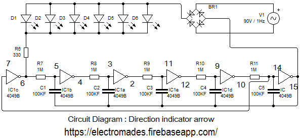
This direction indicator arrow is used to indicate the direction of toilet or any other place. Sometimes when the gathering in a party is large and the guest are unable to find the toilets, food courts or sweet corner etc. This arrow indicator is used to indicate the direction of the toilets, food courts or sweet corner etc. This pointer is very useful for everyone. The circuit is based on a single IC 4049 which contains six CMOS inverters. Each of these has a RC network at its output to provide an appropriate delay before enabling the next inverter. The output of the chip are capable of driving one LED directly. Delay time of LED is controlled by changing the value of the capacitor. Solder all the components on the PCB as per the circuit diagram as a direction indicator.
Circuit Diagram

Components Required
1. Resistances R7, R8, R9, R10, R11,-1MΩ
2. Capacitor C1,C2,C3,C4,C5,-100KF
3. D1-D6-LED
4. IC 4049
5. BR 1(bridge rectifier) uses 1N4007 Diode
Comments & Related items
Popular Posts : Automatic Light | Electronic Dice | Direction indicator | Fire alarm | Touch Switch