Posted by Admin | Leave a Comment
Circuit Description
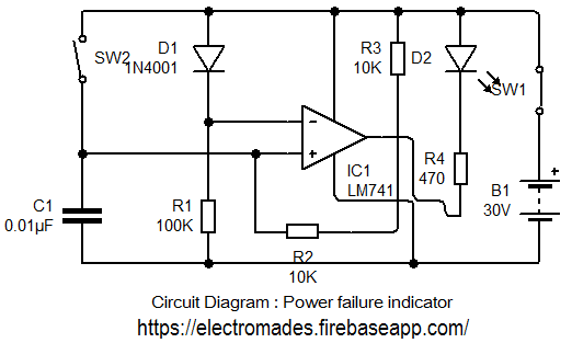
Power Supply failure are very common now days. This circuit indicates power failure by glowing LED. Some of the digital appliances need a continuous power supply to ensure correct operation. A digital clock is an example which needs a continuous supply. If the power fail, we have to reset the clock for correct time. In case of power failure the LED will glow. When the supply is switched on the voltage at pin 2of IC 7841 is 0.6v lower than the supply voltage, pressing the reset button makes pin 3 voltage higher than that of pin 2 and the output swing high.
Positive feedback via R2 makes the circuit latch in this state. The LED is therefore not lit. When the supply is interrupted, all voltage fall to zero. Upon restoration of the supply, the inverting input is immediately pulled up to previous voltage by diode D1.However, capacitor C1 being uncharged, holds the voltage at the non-inverting input low. The circuit stays in this state until reset button is pressed again.
Circuit Diagram

Components Required
1. Reset Switch
2. Capacitor C1 - 0.1µF
3. Resistance-
R1- 100kΩ
R2- 10kΩ
R3- 10kΩ
R4- 1kΩ
4. IC 741(operational amplifier)R2- 10kΩ
R3- 10kΩ
R4- 1kΩ
5. Diode D1- 1N 4001
6. LED
7. Battery 9v or 12v
Comments & Related items
Popular Posts : Automatic Light | Electronic Dice | Direction indicator | Fire alarm | Touch Switch